Actuated Valves
Valve actuation may be manual or automatic. There maybe hundreds of valves on a facility, and there maybe a requirement to have a mix of actuation types. Some valves may be located in remote, extremely hostile or toxic environments that make manual operation not practical and/or safe. Also as a safety feature, certain types of automatic actuators may be required to operate quickly, shutting down a valve in case of emergency
An automatic actuator has an external power source to provide the force and motion to operate a valve remotely or automatically. There are typically three types of power sources for actuation, pneumatic, hydraulic and electric. The choice of power source may depend on a number of factors, availability of the power source, control requirements of the valve, torque required to move the valve.
The different types of actuators used on valves discussed in the following are Manual Actuators, Pnuematic Actuators and Hydraulic Actuators:
Manual Actuators
A manual actuator utilises levers, gears, or wheels to facilitate movement of the valve manually.
Advantages of Manual Actuators
Dis- Advantages of Manual Actuators
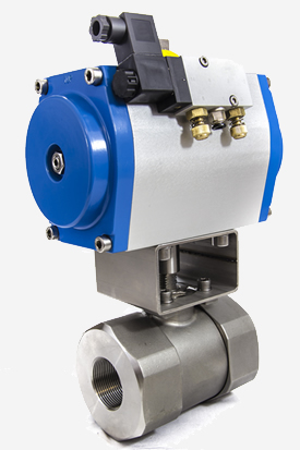
Pneumatic actuators use pressurized air to operate a valve. They do this by applying the force of the air to a piston or a diaphragm attached to the valve stem. Pneumatic actuators are used to provide automatic or semi-automatic valve operation, and are the most popular type in use due to their dependability and simplicity of design.
Advantages of Pneumatic Actuators
Dis-Advantages of Pneumatic Actuators
Hydraulic Actuators
Hydraulic actuators use a pressurized fluid to control valve movement. The hydraulic fluid used is either water or oil and is fed to either one or both sides of a piston to cause movement. Hydraulic valves provide for automatic and semi-automatic valve operation.
Advantages of Hydraulic Actuators
Dis-Advantages of Hydraulic Actuator
Electric Actuators
Electric actuators include electric motors and solenoid-actuated valves. Electric motors can be used to open, close, and position a valve manually, automatically, or semi-automatically. The motor operates in both directions and drives the valve stem by means of gear couplings. Electric actuators are frequently used on multi-turn valves such as gate or globe valves. With the addition of a quarter-turn gearbox, they can be utilised on ball, plug, or other quarter-turn valves.
Solenoid valves use electric power to attract a magnetic slug attached to the valve stem and are used in automatic open-close applications. Solenoid valves are often used as pilot valves.
Advantages of Electric Actuators
Dis-Advantages of Electric Actuators
Common Terms and Defintions Used for Electric, Pnuematic and Hydraulic Valve Actuators
| Term | Definition |
| ambient temperature | environmental temperature of the location where the actuator is working |
| blistering | formation of bubbles or pimples on a coated surface, caused by the local loss of adhesion and lifting of the film from the underlying substrate |
| emergency closing/opening |
overriding operation allowing the actuator to be closed or opened under emergency conditions |
| emergency shut down | specific function of an actuator designed to perform a pre-determined operation (open/close/stayput) in an emergency situation |
| end of travel | predefined position related to a fully open or a fully closed condition |
| end stop | mechanical part, designed to stop the actuator drive train at an end position |
| end torque/thrust | actuator maximum output torque/thrust available at the end of the stroke |
| fail-safe actuator | multi-turn, part-turn or linear actuator which is able to operate in a defined pre-determined way on loss of external power |
| fail-safe position | defined pre-determined position in which the actuator operates on loss of external power |
| indicating arrangement | device, externally visible, showing the position of the actuator/valve obturator |
| limit switch | contact that changes status when the stroking position of the actuator reaches a preset position |
| linear actuator | actuator which provides thrust for a defined linear stroke |
| manual override | device designed to operate manually the valve when required |
| motive energy | energy used to operate the actuator which can be electric, pneumatic or hydraulic |
| operating cycle | one complete opening and one complete closing stroke of the valve, including the stopping phases |
| operating/stroking time |
duration of a complete stroke of the actuator |
| output torque/thrust | torque/thrust delivered by the actuator |
| position transmitter | device transmitting a signal proportional to the actuator position |
| rated torque/thrust | characterising figure indicated by the actuator manufacturer used to define the maximum actuator operating torque/thrust capability |
| test room temperature | ambient air temperature where the actuator is tested |
| run torque/thrust | actuator output torque/thrust developed between the seating/unseating positions |
| seating/unseating torque | actuator output torque required to seat/unseat the valve |
| start torque/thrust | actuator output torque/thrust at the beginning of the stroke, in the direction of the motive force defined |
| stroke | single and complete movement from one end of travel to the other |
| torque/thrust characteristics | values which may vary through the actuator stroke |
| travel limitation | any device integrated in the actuator and designed to limit the travel/stroke |
| travel | value of actuator output turns, angular or linear movement between ends of travel |